- CE and IEC Conformity
CE The European Union has enacted comprehensive directives for product safety and environmental compatibility. These regulations are being continually extended and provide, implemented in the respective national legislation, for the safe use of products by the user as well as the proper disposal of equipment after the end of its service life. A manufacturer confirms that his product, when marked with the CE sign, conforms to the relevant regulations.
IEC Is the International Electrical Commission. It establishes international standards for electrical and electronic equipment and components. With EU agreement and ultimately national standardisation and legislation, these recommendations become binding.
An example of IEC and CE conformity: Loudspeaker connection terminals on audio equipment and indeed loudspeakers and amplifiers in general must be shock hazard protected, as long as it cannot be ruled out that they produce more than 34.5 volts at the loudspeaker terminals. As a consequence, WBT offers an ever widening range of fully insulated pole terminals. With the newest product, the nextgen terminal WBT-0710 we have succeeded in concealing the insulation beneath polished metal. In addition, for some time now, loudspeaker plugs may no longer be offered in a ‘plugged-in condition’ with a bare metal conductor area. (See the Safety Pin Banana WBT-0645 and the Sandwich Spades WBT-0680/-0660, whereby the Safety Pin, which may not be permitted in accordance with the ban on standard banana plugs derived from the CE, can be used because of the shock hazard protection). The fact that loudspeaker amplifier connections must be performed with cables which require a plug or similar connection at both ends continues to be a safety problem, when loudspeaker ratings of more than 150 watt are ‘plugged’.
- Characteristic Impedance
Whoever has seen a picture on their television with double outlines (ghosting), or failed to get a connection on their ISDN telephone or data link because of faulty termination impedance, or stood in front of a damaged microwave in which unsuitable crockery has been placed, has been a witness to a mismatch and indeed mismatches from characteristic impedance which is the result of damaging reflection s. It is not only the so called performance matching between an electrical generator and a consumer load, which is necessary to pass on the maximum performance from the source but also the matching of a running interconnection at the source on one side and at the load on the other side which is responsible for the avoidance of temporally reflections. Since it is scarcely possible to match impedance (the name for a general complex resistance) from one end of a circuit to the other, the designated circuit with its characteristic impedance is given the value of the source and load impedance, which is necessary for reflection free, undisturbed signal transmission. The designation of the characteristic impedance of cable, frequency independent in Ω shows that the model or rather the approximation of a low loss or loss free set-up is the basis. However, it cannot be denied that it is the reactive part of the conductor geometry (inductance and capacitance) which oppose the propagation of current and voltage state (the so called waves) resistance. Their size is intrinsically controlled through the geometry, ohmischer looped resistance and isolation loss and for real audio current generally negligible. Due to the fact that the geometry of RCA connectors, the bodies of which are conductors, have in their base form a feasible resistance of between 15 Ω and 45 Ω in the best case, must the full metal form be designed as a bifilar arrangement, in consideration of the geometric dimensions, so that, with a 75 Ω characteristic impedance, a reflection free operation with a suitable cable can be made.
Characteristic Impedance
Surge Impedance Any signal path should be configured in that way, that source ↔ connection elements ↔ transmission line connection elements ↔ load all have identical (characteristic) impedance (i.e. the commonly complex form of a general resistance). The small signal connections of audio devices for instance are obviously suited for engaged steps in this direction. Such steps are supported by the established technology of broad band transmission and measurement. They offer well proved connection and transmission elements with defined characteristic impedance values (50 Ω, 75 Ω, ., ... )
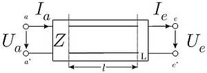
Fig.1: Phenomenology of transmission line The characteristic impedance of an electrical topology – in our case that of a line element – will be evaluated numerically in 'Ohm' like any other resistance, regardless whether it is purely resistive, reactive, or complex, but that is the only property it has common with the evaluation of discrete electrical components. In all cases of discussing electrical arrangements where the propagation velocity of voltage and current states within the topology is of importance the phenomena of wave propagation have to be considered. This requirement applies for power lines, data highways, microstrip devices, etc. and of course hifi connections. There are two principally different ways to become familiar with the understanding of the time and space depending properties of wave propagation on transmission lines. One approach is offered by the network theory by modelling the line by elements derived from the discrete passive elements R, L, and C. But for our purposes another way, the physically based phenomenological approach will better meet our simpler requirements. Look at Fig.1: When connecting a voltage Ua to the input a-a' of a line (coax, twisted pair …) then a current Ia(t=0) will flow into this port. This current will not depend on the condition defined at the port e-e', it may be short circuit, open-circuit or terminated any way. Only after a certain time tl (1 to 2 ns for 30 cm connection length for instance) the input state reaches the port e-e' (lossless line assumed). If this port is connected to an impedance Ze=Ua/Ia everything is in order. The current Ia may go out as Ie and the voltage Ua may go on to feed Ia into the input. For all other cases, short circuit, open-circuit or line terminated with an impedance Ze ≠ Ua/Ia, at e-e' a correcting state will be generated which corresponds to conditions at e-e'. I.e. for instance that at an open circuit end will generate a state –Ia into direction a-a' because at an open circuit the current has to be zero. This correction state arrives after a time tl at a-a' and superposes the current Ia(2 tl ) going in there at this time. The resistance – commonly impedance - a line opposes states streaming in or surging in is called surge impedance or characteristic impedance (derived from network theory). The phenomenological point of view gives an evident insight to our main problem discussed here: the insertion of plug connections into a transmission line. As result we can state that we have to avoid any mismatch (Zplug ≠ Zline ) of impedances within the chain defined in the first sentence of this section. As shown any mismatch will generate multiple reflections at all points of impedance imparity and cause measurable and hardly measurable but audible distortions. The best way to achieve the necessary impedance matching for a sufficient frequency range is to aim at broadly used impedances (e. g. 75 Ω). The specification of cable impedances, frequency independent in Ω, suggests that the base generally used is the lossless or low loss approach. It is not only the so called power matching between an electrical generator and its load, which is necessary to get the maximum power from the source, but also the matching of a time consuming transmission line to the source at one end and to the load at the other end, which is responsible for the avoidance of temporally resoluted reflections. Since it is scarcely possible to match a transmission line to different impedances (the name for a complex resistance) at each of its ends, the characteristic impedance of the used transmission line will define the source impedance as well as the load impedance to obtain the desired reflection free and undisturbed signal transmission.
The designation of the characteristic impedance of a cable, frequency independent in Ω shows that the model respectively the underlying approximation commonly used is that of a low loss or lossless device. Nevertheless it should not be forgotten that the reactive parts defined by the line or connector geometry (inductance and capacitance) oppose the propagation of current and voltage states (the so called wave) resistance. Their size is intrinsically controlled through the geometry. Loop resistance and isolation loss are, for audio lines, generally negligible. Due to the fact that the given geometry of a RCA connection - which is an essential part of the transmission device discussed here - in its basic form allows characteristic impedances between 15 Ω and 45 Ω the full metal form had to be rearranged as a bifilar design in order to achieve reflection free operation in widely used 75 Ω surroundings. - Contact Microphone
When two electrical conductors are mechanically joined, an electrical resistance forms between the two conductors. This resistance depends on several factors, among them, from the mechanical force with which the two conductors are pressed together. The greater is the force, the smaller the resistance. If the contact point vibrates or resonates, this force can change considerably in frequency with the vibration so that the signal is transmitted better or worse in this rhythm. This effect occurs most often with loudspeakers and can be clearly heard as a distortion to the signal. Manufacturers of loudspeakers have made considerable efforts to construct their chassis’ to be as passive as possible. Nevertheless, vibrations cannot be completely eliminated and these transmit themselves to the binding posts.
- Crimpanschlusstechnik / Crimpen
The crimp connection technique was developed for the use of screwed connections with stranded cable. Stranded cable is cable which has its conductor made from a large number of thin wires which have been twisted together rather than cable with one single thick wire. These thin wires can easily break-off with a screw connection. In addition, they can evade the screw. A reliable and stable connection is therefore not possible. During crimping, a cable end sleeve is inserted over the end of the stripped stranded cable. The sleeve is then pressed together with crimping pliers. The material then ‘flows’ together as a result of the forming pressure of the pliers creating a homogenous copper rod. This connection can now be either screwed in to a crimp plug with a grub screw or fixed in a terminal. In addition to standard cable end sleeves, WBT also offers sleeves with injection moulded plastic collars. When using this version, the sleeve is pushed further over the stripped area so that the collar reaches over the cable insulation. This way, the kink sensitive area between the cable sleeve and cable insulation is protected during bending. This is particularly important if the cable is to be frequently moved. Crimping is a far superior connection technique for stranded cable in comparison to soldering when cable with a thick cross-section should be soldered, since the possibility of a so called ‘cold’ soldered joint exists. In such a case, an air bubble can form under the cold solder which keeps the joint chemically active and susceptible to surface corrosion. The deciding advantage of crimping is also that neither soldering material (flux and solder), nor heat are required. Solder is a mixture from, among others, tin, flux (mostly aggressive) and a small part of silver. The solder joint is therefore always seen as the weak point of conductor contact. Heat affects not only the conductor and insulation material but it is also capable of releasing gases from the PVC of the cable sheath which can form on the contact point and remain chemically active. Crimping on the other hand has none of these disturbing characteristics. The cable end sleeves from WBT are available in pure copper (Cu) or fine silver (Ag) and have no negative effects on the conductivity of the cable. In addition, the fixing by means of the grub screw, provides an excellent mechanical stability and keeps the transition resistances to a minimum. Crimp connectors usually require more fabrication complexity. At WBT all crimp connectors possess Torx screws with a special fine thread. This guarantees that a one time applied pressure will be perfectly held. Crimp connectors are re-useable.